The Power Behind the Port: Sizing PoE for a Small UK Network
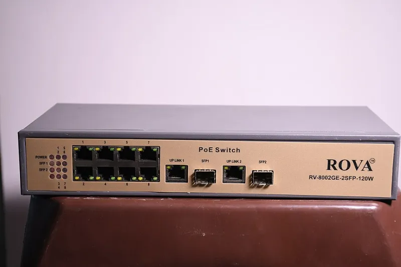
Photo: Bkvrova, CC BY-SA 4.0, via Wikimedia Commons
Adding a fourth camera and a second access point is rarely a cabling problem. It is an arithmetic problem, and the arithmetic usually starts with a number printed on a switch box. A small PoE switch may claim 120W of budget, while the devices attached to it claim 8W each. Neither figure is false on its own. The mistake is assuming they can be compared directly.
Power over Ethernet is a negotiated supply, not a simple sum of nameplate labels. A realistic budget has to account for what the switch can allocate, what the powered device actually draws, what the cable loses on the way, and what happens when everything boots at once. Get those four things into one spreadsheet and the upgrade path becomes much less mysterious.
Start with the switch, not the shopping list
The first number to find is the switch's total PoE power budget. This is the shared pool for all PoE ports, not a per-port allowance. A unit with eight PoE ports and a 120W budget cannot deliver 30W on every port simultaneously, even if each port is advertised as 802.3at capable. Some switches also impose a lower per-port limit or reserve power by class, so the datasheet deserves a careful read rather than a glance at the headline wattage.
The relevant standards are worth keeping straight. 802.3af, often called PoE, supplies up to 15.4W at the switch and guarantees roughly 12.95W at the device. 802.3at, or PoE+, moves that to 30W at the switch and 25.5W at the device. 802.3bt adds Type 3 and Type 4, with 60W and 90W at the power sourcing equipment and 51W and 71W at the powered device. Marketing labels such as PoE+ and PoE++ are useful shorthand, but the class and the datasheet matter more.
The three numbers that matter
For planning purposes, keep three figures separate. The first is the power sourcing budget: what the switch can allocate across its ports. The second is the powered device draw: what each camera or access point actually consumes in normal operation. The third is the loss between them: cable resistance, connectors, and the fact that a long run at high current is not a perfect pipe.
Nameplate wattage is usually a maximum, not a typical. A camera rated at 12W may draw less with infrared off, and an access point rated at 20W may peak only during boot or heavy radio activity. That is useful for UPS sizing, but it is dangerous for switch planning. Many switches allocate by class, so a Class 4 device may reserve 30W even if it normally draws 10W. If the switch supports LLDP power negotiation, it may refine that reservation, but do not assume every cheap unmanaged switch does.
Cable loss is the quiet variable. Cat5e and Cat6 are not interchangeable when a long run is close to its limit. At 100 metres, a quoted device wattage should be treated as a ceiling rather than an entitlement. Use a 10 per cent allowance for short, cool indoor runs and 20 per cent for long, warm, or outdoor paths. That allowance is not a substitute for a cable tester, but it stops a plan from being optimistic before anything is plugged in.
A spreadsheet that tells the truth
A simple sheet is enough. Use one row per device and columns for location, device type, PoE class, switch allocation in watts, measured or nameplate draw, quantity, startup factor, cable allowance, and line total. Keep two totals: allocated watts for switch sizing and actual watts for UPS and heat calculations.
A workable formula is: line total equals quantity multiplied by the greater of the switch allocation or the device draw with a startup factor, then increased by the cable allowance. The startup factor can be 1.2 for cameras and access points, higher for pan-tilt-zoom units with heaters. The cable allowance is the percentage you chose for that run. Add a spare capacity line of 20 to 25 per cent. That spare is not padding; it is what lets you add a camera without replacing the switch next year.
As an example, six cameras allocated at 30W each and three access points allocated at 30W each come to 270W of switch allocation. The actual draw might be only 130W. A 240W switch may run those devices in practice but refuse the last port during boot or after a firmware change. The allocation total is the safer number for buying decisions.
Startup, winter and the UPS
Startup behaviour deserves its own line. Cameras with infrared illuminators and mechanical pan-tilt heads can pull more at power-on than in steady state. Access points may briefly draw more while radios initialise. Managed switches often stagger PoE port power-up, which helps, but unmanaged units may not. If the switch is already close to its budget, a cold morning restart can expose the shortfall.
UPS sizing is a separate calculation. A UPS is rated in volt-amperes and watts, and the power factor matters. Do not size a 300W load against a 300VA UPS and expect headroom. Add the PoE switch, router, network video recorder, and any injectors, then leave 30 per cent capacity for runtime and battery ageing. In a UK office or home lab, a short power cut is not the only risk; a brownout can cause repeated reboots that are harder on equipment than a clean shutdown.
Heat is the final overhead. PoE power that leaves the switch as electricity arrives at the device largely as heat. A cupboard full of cameras, access points and a switch needs ventilation, even if the wattage looks modest on paper.
Injectors and the temptation to patch around
Single-port injectors are a legitimate fix for one camera in a difficult location. They are not a free expansion of the switch budget. Each injector needs a mains socket, and ideally the same UPS protection as the switch. Passive injectors that send non-standard voltage down a cable can damage equipment; use a proper 802.3af or 802.3at injector and check the voltage and pinout. Midspans are neater in a rack, but they still consume rack space, power outlets and UPS capacity.
Injectors also complicate fault-finding. A camera that reboots may be failing negotiation, not losing data. Label every injector and record it in the spreadsheet. If the count of mains adapters is rising, the honest answer is usually a larger PoE switch rather than a pile of injectors.
An upgrade path that does not brown out
Begin with an audit: read the switch's PoE status page or use a tester to record actual draw per port. Then list the devices you intend to add over the next 18 months, not just today. Choose a switch whose allocated budget covers that list plus 25 per cent. For a small UK network with six cameras and three access points, a 370W to 400W switch is often the sensible landing point; for two access points and three low-power cameras, a 120W unit may be adequate if the allocation maths supports it. Split cameras and access points across two switches only if you can manage the extra uplink and power draw.
Finally, stage the rollout. Add one device, check the switch's budget and temperature, then add the next. A PoE plan is not a count of ports. It is a power plan, and it should be tested before the cameras arrive.